What is Tangential Flow Filtration (TFF) and Where is it Used?

What is Tangential flow filtration?

Tangential Flow Filtration

Tangential flow filtration (TFF), also known as Cross-flow filtration, is a process of separation widely used in bio-pharmaceutical and food industries. It is different from other filtration systems in that the fluid is passed parallel to the filter, rather than being pushed through a membrane perpendicularly which can clog the filter media. This method is preferred for its continuous filtration and reproducible performance. The particles that pass through the membrane, the permeate, are put off to the side, while the rest, the retentate, is recycled back to the feed.

When is TFF used?

Tangential flow filtration is used in concentration and diafiltration processes.

  • Concentration – Increases the concentration of a solution by removing fluids while keeping the solute molecules. This process is done by selecting a filter significantly smaller than the solute molecules to allow for a higher retention of solute molecules.
  • Diafiltration – The separation of small and large particles, leaving the smaller particles behind without altering the overall concentration at the end by washing out the remaining salt with another buffer. This process can also reduce the concentration of a solution by washing out the remaining salts with water.

Specific applications of TFF include, but are not limited to:

  • Pre-filtration component WFI systems to remove endotoxins.
  • Recovering of bacterial cultures and viruses.
  • Removing PVA that is excreted from the excipient from nanoparticles during drug loading.


References

Carole S. Genovesi, May-June 1983, Several Uses for Tangential-Flow Filtration in the Pharmaceutical Industry, Accessed on 28 August 2018. <http://journal.pda.org/content/37/3/81.abstract>

Pall Corporation, n.d., Introduction to Tangential Flow Filtration for Laboratory and Process Development Applications, Accessed on 28 August 2018. <https://laboratory.pall.com/content/dam/pall/laboratory/literature-library/non-gated/id-34212.pdf>

Gautam Dalwadi and Vivian Bruce Sunderland, 26 September 2008, Purification of PEGylated Nanoparticle Using Tangential Flow Filtration (TFF), Accessed on 28 August 2018. <https://www.tandfonline.com/doi/full/10.1080/03639040601180143?scroll=top&needAccess=true>

Novasep, n.d., Industrial cross-flow filtration technology (Picture), Accessed on 28 August 2018. <https://www.novasep.com/technologies/industrial-cross-flow-filtration-technology.html>

USP Class VI Testing

What is USP Class Testing?

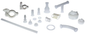
Plastic Sanitary Tri-Clamp Fittings

USP Class testing is one of the most common methods of testing to determine bio-compatibility of materials. There are six classes, VI being the most rigorous. Class VI testing is aimed to certify that there are no harmful reactions or long-term bodily effects caused by chemicals that leach out of plastic materials. USP Class Testing standards are determined by the United States Pharmacopeia and National Formulary (USP-NF), the organization responsible for the quality and safety of medical devices and foods. Class testing is frequently conducted on plastic materials that come in contact with injectable drugs and other fluids found in various steps of the drug manufacturing process.

USP Class VI Testing Methods

USP Class VI testing is conducted by producing an extract of the product with different extraction fluids, such as polyethylene glycol and vegetable oil, and injecting it in specimen (rabbits and mice) in vivo (alive), to observe the biological response to the extract. Testing is commonly done as per USP <88>, which requires three types of testing: systemic injection, intracutaneous, and implantation.

  • Systemic Injection Test (Acute Systemic Toxicity):
    Test specimen are injected with the extract intravenously and observed for 72 hours. The specimen are monitored for any abnormal toxic reactivity. The scientist determines the test as pass/fail.
  • Intracutaneous Test:
    The purpose of this test is to check for any local skin reactions. Test Specimen are injected with the extract intracutaneously and observed for 72 hours. The reactions are scored and averaged.
  • Implantation Test:
    Specimen are implanted with the product material to observe the reaction of the live tissue in direct contact with the product over a span of at least 120 hours (5 days).

Why should products be USP Class VI?

Class testing is often required for manufacturing drugs for its low toxicity compliance and strict bio-compatibility standards. It is important to know that no fluid-contact surfaces will result in harmful chemicals being extracted in to a conveyed fluid. Class VI testing extensively investigates the reaction in the body, skin, and living tissue to ensure safety. USP Class VI is a common standard for pharmaceutical tubing, fittings, single-use systems, and fabricated parts.

References:
Unites States Pharmacopeia, n.d., <88> Biological Reactivity Tests, In Vivo, accessed 21 August 2018, <http://www.pharmacopeia.cn/v29240/usp29nf24s0_c88.html>.
NAMSA, 14 April 2014, USP Class Testing, accessed 21 August 2018, <https://www.namsa.com/toxicology/usp-class-testing>

WFI Basics and Sampling Methods

What is Water For Injection (WFI)?

Water For Injection is a solvent that is used for the manufacture of injection drugs. It can be used as an excipient as well as the final cleaning rinse agent for Bulk Active Pharmaceutical Ingredient (API) or in a Bulk Pharmaceutical Chemical (BPC) preparation.

Types of Water For Injection

  • USP WFI – USP WFI is the material used to make Bacteriostatic and Sterile WFI. It is not the finished product, therefore, it needs to go through extensive validation to ensure that it meets USP parameters.
  • USP Bacteriostatic WFI – Bacteriostatic WFI is sterile water that has 0.9% benzyl alcohol added as a preservative. It prolongs the water vial for up to 28 days, therefore, allowing repeated usage.
  • USP Sterile WFI – Sterile Water For Injection is stored in a single-use vial and used for intravenous administration. After it is opened or heated, it cannot be reused and must be discarded.

How is Water for Injection Made?

  • Distillation – According to USP, European Pharmacopoeia (EP), and Japanese Pharmacopoeia (JP) guidelines, distillation is the preferred method of manufacturing WFI for its ability to remove 100% of all impurities. Pre-treated water is boiled and the clean water vapor is collected, leaving all impurities behind. The collected vapor then undergoes condensation to return to its liquid state.
  • Reverse Osmosis and Ultra-Filtration – Reverse Osmosis (RO) is permitted by USP and JP regulations, however, JP regulations require ultra-filtration if reverse osmosis is utilized. The water first goes through ultra-filters that ‘squeeze’ water and small impurities through a semi-permeable membrane. Next , the ultrafiltered water passes through a semi-permeable RO membrane which further separates the water and impurities by forcing the water through RO membranes leaving pure water.

Regulations and Sampling

As per USP < 1231>, WFI needs to meet these requirements:

Total Organic Carbon (TOC) [µg C/L, ppb]<500
Conductivity at 25°C (µS/cm)<1.3
Bacteria (CFU/100 ml)<10
Endotoxin (EU/ml)0.25


These levels are monitored through test analysis and sampling periodically. Sampling is done through valves that are located throughout the system. Since WFI needs to be completely rid of microbes, the water needs to be in constant movement at 80-90°C so that microbial growth cannot occur. In order to ensure water quality is within specification, sampling is performed frequently at different use-point valves to ensure that there are no contaminants. The samples are collected and taken to a microbiology laboratory for testing per USP <1231> requirements.

Sampling Process

The collection and testing processes are critical procedures that need to be performed by highly trained technicians to avoid false-positive results due to contamination during the collection by improper techniques, poor hygienic habits, or inadequate sterilization methods. Oftentimes, companies sterilize their sampling equipment using autoclave and then create a kit for collection. Before collecting the sample, the valve is inspected for cleanliness and it is flushed for 30 seconds or more at a rate of 8 ft/s or more in order to remove bio-film structures.

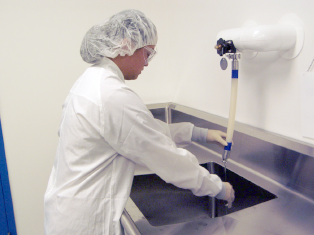
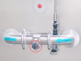
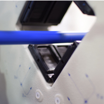
The pictures below depict the sampling procedure in progress (left) and it shows an example of a use-point valve (right) from where water is collected for sampling.

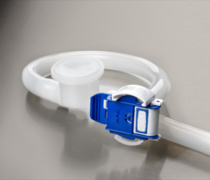
During collection, technicians have to manually place a gasket onto the flow path before clamping the sample device into the use-point valve. Placing the gasket poses a tremendous risk of contamination because the technician touches parts where the sample will flow, compromising the integrity of the results. Whenever a result is positive, costly measures are taken to investigate the source of contamination and the problem is often traced back to the collection procedure, not the system itself. This problem can be easily solved through single-use systems like our aSURE™ WFI Sampling Kit or aSURE™ Tri-Clamp Fittings. These sanitary connections come with a fused gasket, which allows the technician to successfully collect a sample without coming into contact with the fitting, removing an immense contamination risk. Our kits are gamma-radiated for microbial control, double bagged in dual laminate medical-grade pouches with easy-peel seals.

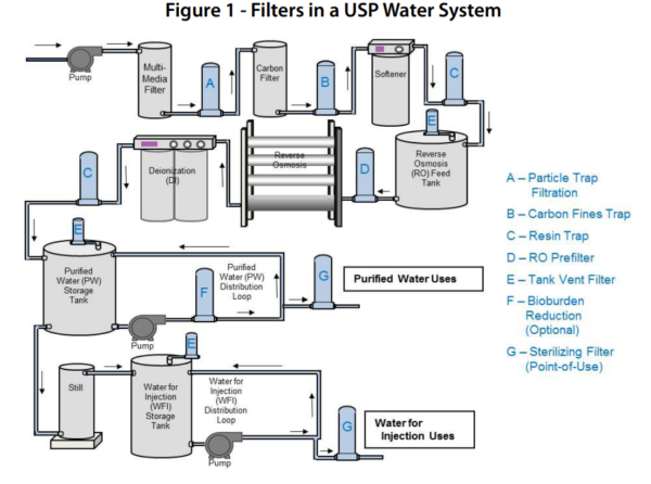
Example of a WFI Filtration and Storage System:


References

Mettler Toledo, Pharmaceutical Waters Guide, accessed 16 August 2018, <http://www.modcon.co.il/wp-content/uploads/cmdm/3793/1439448823_IB_Pharma_Waters_Guide_EN_Jan2013.pdf>.

U.S. Food & Drug Administration, 7/93, High Purity Water System, accessed on 16 August 2018, <https://www.fda.gov/iceci/inspections/inspectionguides/ucm074905.htm>.

U.S. Food & Drug Administration, 12/31/86, Water For Pharmaceutical Use, accessed on 17 August 2018,
<https://www.fda.gov/iceci/inspections/inspectionguides/inspectiontechnicalguides/ucm072925.htm>.

Pure Flow Inc., Spring 2015, How to Properly Sample Water Systems, accessed 17 August 2018, <https://www.pureflowinc.com/wp-content/uploads/2015/09/PFI-Newsletter-1503.pdf>.

United States Phamacopeia, <1231> WATER FOR PHARMACEUTICAL PURPOSES, accessed on 17 August 2018, <https://hmc.usp.org/sites/default/files/documents/HMC/GCs-Pdfs/c1231_1SUSP40.pdf>.

Critical Process Filtration Inc., (n.d.), Filters in USP Water System [Diagram], accessed 17 August 2018, <https://www.criticalprocess.com/WaterTreatment/pdfs/App_Summary-Bioburden_Control_in_USP_Water_Systems.pdf>.

Additional Photo Credit: MQA Laboratories

Differences Between Cleanroom Classes

What is a Cleanroom?

A cleanroom is a space in which the number of contaminants in the air per unit of volume, such as dust and other airborne microbes sized between 0.1µm and 5µm, are controlled to decrease chances of contamination. These particles are controlled by a high efficiency particulate air (HEPA), which filters the air before entering the cleanroom, and it is changed multiple times per hour, according to the class of the cleanroom, as established by the International Standard Organization (ISO) 14644-1. Cleanrooms with the intention of keeping a product without contaminants are kept at a positive pressure so that the particles flow out, from the cleanest area to the least clean one. However, there are cleanrooms kept at a negative pressure in order to not let anything escape the cleanroom, such as quarantine stations and chemical testing facilities.

At TBL, we are equipped with an ISO Class 7 & Class 5 Cleanrooms. Our cleanrooms feature UV lights designed to kill most germs. These cleanrooms are utilized for assembling single-use systems packaging and injection molding.

Clean-room assembly of single-use tubing kits and manifolds. Gamma irradiation available

Cleanroom Regulations

The first cleanroom standard was the US Federal Standard 209E. This regulation separated cleanrooms into classes, Class 1 having the lowest count of particulates per cubic meter, while Class 100,000 had the highest. As cleanrooms became more prominent throughout the world, an international standard became a necessity. The International Standard Organization assembled a committee and developed the ISO 14644-1. It was based on the Federal Standard 209E, but it had two more classes before Class 1, and one more after Class 100,000 to represent room air. The ISO 14644-1 superseded the FS209E in 2015.

Current Cleanroom Classes

The table below shows how the classes are divided by the number particles allowed per cubic meter along with the range of air changes per hour in each class.

Number of Particles per Cubic Meter by Micrometer Size
Class0.1 micron0.2 micron0.3 micron0.5 micron1 micron5 micronsAir Changes per Hour
ISO 11021.020.350.0830.0029360-600
ISO 210023.710.23.50.83.029360-600
ISO 31,000237102358.30.29360-540
ISO 410,0002,3701,020352832.93300-540
ISO 5100,00023,70010,2003,52083229.3240-480
ISO 61,000,000237,000102,00035,2008,320293150-240
ISO 7352,00083,2002,93060-90
ISO 83,520,000832,00029,3005-48
ISO 935,200,0008,320,000293,000

How to Determine Tubing Burst Pressure and Working Pressure

How to determine the pressure rating of tubing?

To ensure that your desired tubing is fit for your needs, one must understand how pressure ratings affect different materials. If the material is chosen for inappropriate use, it can burst at the most inconvenient time; however, this can be prevented by using Barlow’s formula, which shows the theoretical maximum operating pressure of a tube by using its tensile strength at yield (maximum pressure at which there is no permanent damage) and its interior and exterior diameters. This formula can be used for all of your tubing needs, as it is based on a 4:1 safety factor, which is appropriate for compressed air and gases, as well as fluids with working pressure greater than 1MPa.

Barlow’s Formula

barlow's formula for calculating tubing pressure rating

Burst Pressure in MPa or psi
Tensile Strength @ Yield in MPa or psi
X= OD/2 in inches
Y= ID/2 in inches

Tensile Strength Values

Click on a product to be redirected to its page.

MaterialProductTensile Strength @ Yield (psi)Tensile Strength @ Yield (MPa)
Phathalate Free VynilClearGreen®190013.1
ClearGreen®60170011.7
Silicone (Non-Braided)Platinum Cured Silicone12008.3
Peroxide Cured Silicone159511
TPEPharm-A-Line™ I972 (At Break)6.7
Pharm-A-Line™ VI210014.5
Weldable TPECellGyn®8706
PFAFluor-A-Pure™ PFA420028.9
FEPFluor-A-Pure™ FEP400027.5
PTFEFluor-A-Pure™ PTFE350024.1
PVDFKynar-Flex®2000-310014-21
LDPELDPE170011.7
LLDPELLDPE217015


Note: These are theoretical values. Material properties may be affected greatly by temperature, operating pressure, chemical concentration, the presence of other chemicals, and other factors. Ultimately, users should determine the compatibility of any product through field testing under their particular process conditions.

Choosing Tri-Clamp Fittings for Your Application

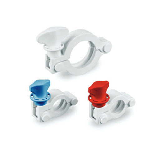
Tri-clamps are one of the most common types of pipe connections in the food, beverage, biotech, and pharmaceutical industries. This type of connection consists of a gasket compressed between two tri-clamp ferrules or flanges which are mechanically compressed in place with a clamp. Tri-clamp fittings are available in a variety of sizes, can be constructed from either steel or plastic, and can be either permanent or temporary. The clamp itself also comes in a variety of designs for ease of disassembly and cleaning.

It is therefore essential to select the right type of tri-clamp fitting to ensure the connection operates effectively in a given application. Choosing the right size and type of fitting can help minimize or eliminate contamination, bacterial growth, leaks, and deterioration of the connection material.

Common Applications for Tri-Clamp Gaskets & Tri-Clamp Fittings

Tri-clamp fittings and gaskets are typically used in hygienic or sanitary fitting applications. That is, they are ideal for the transportation of liquids that require a high degree of purity with minimal risk of contamination.

In the pharmaceutical, biotech, and food and beverage industries, disassembling, cleaning, and reconfiguring clamp connections are critical to maintaining a sterile environment that complies with various industry regulations and standards. Inappropriate connections can trap contaminants and harbor bacteria which can potentially ruin batches of process fluids with costly implications.

Tri-clamp connections provide a smooth, non-contaminating internal pipework joint. The connections consist of no threads, pockets, or tight radii which tend to form entrapment areas that can promote the growth of microorganisms.

How to Choose the Right Tri-Clamp Connection

Selecting the most suitable tri-clamp fitting usually begins with proper material selection. When choosing between steel or plastic, one must first analyze the operating environment. Some of the primary factors that need to be considered include:

  • Temperature range
  • Pressure range
  • Flow rates
  • Fluid compatibility
  • Environmental exposure

While stainless steel may be suitable for extremely high-temperature and high-pressure applications, these environments are seldom found in the pharmaceutical and biotech industries. Generally, plastic is adequate for most environments, particularly in applications where the connection is subject to regular assembly and disassembly. Plastic tri-clamp fittings have the advantage of being extremely versatile.

Plastic fittings are available in a variety of polymer compositions and can be customized for efficient operation in various environments. In most applications, polypropylene fittings provide sufficient mechanical, chemical, and functional properties for single-use systems. Other polymer resins commonly used to manufacture tri-clamp sanitary fittings include polycarbonate, polyvinylidene fluoride (PVDF), and polysulfone.

Once the appropriate material is determined based on the operating environment, the proper fitting size should be selected. When determining the correct tri-clamp size, it is important to remember that the size of the fitting is based on the outside diameter of the tubing and not the diameter of the flange. This distinction is crucial since the flange is typically approximately ½-inch wider than the tubing. For example, if you were to specify a 2-inch tri-clamp fitting based on the flange dimension, upon installation you would find the fitting to be ½-inch too large.

Another essential element to proper sizing is gasket selection. When joining pairs of differently sized tubing, the gasket should be sized for the larger tube size to ensure a tight fit at the connection. Gaskets that are sized for the smaller tube diameter can result in excess unclamped gasket material. This area of loose, overhanging gasket can trap bacteria and run the risk of contamination.

Lastly, to complete the connection, the gasket clamps are available in three distinct designs: two-segment (single hinge), three-segment (double hinge), and high-pressure (no hinge). The ¾-inch clamp is typically only available in two-segment types.

Larger sized clamps are available as both two and three-segment types. Although both clamps offer similar performance, the three-segment clamp can be more expensive. However, the three-segment clamp has the added benefit of being easier to install in tight spaces. Ultimately, the choice between the two clamp types is a matter of user preference.

The high-pressure (no hinge) clamp consists of separate clamp segments that are bolted together in place. This type of clamp design is best suited for permanent or semi-permanent applications where frequent disassembly and maintenance is not required. Additionally, high-pressure clamps are ideal in situations where the fluid exerts high pressures and fluctuating temperatures on the tubing.

Learn More

Sanitary gaskets, although commonly used, are not without issues. First, for the connection to work efficiently, the gasket needs to be properly aligned with the ferrule flanges to avoid flow obstruction, pressure buildup, and contamination of the process material. Conventional gaskets are traditionally manually aligned and as a result, are prone to human error during installation.

To address this issue, TBL Performance Plastics has developed the aSURE™ tri-clamp fitting with a built-in gasket. This integrated gasket design combines the gasket and the ferrule fitting into a single component manufactured without using adhesives or clips to keep the gasket in place.

The built-in design guarantees accurate alignment, allows for easier installation, and eliminates the possibility of using the wrong gasket material for the given application. These benefits yield significant cost savings due to the elimination of product contamination and waste.

TBL Performance Plastics has been custom-fabricating FDA regulated products for numerous industries – including the life sciences, biotech, pharmaceutical, and other high-purity markets – for over 16 years. Our engineers have designed the aSURE™ sanitary tri-clamp fitting to ensure compliance with the strictest industry standards.

If you would like to know more about the aSURE™ features, benefits, and technical specifications download our Tri-clamp fitting brochure.

For more information on how the aSURE™ can be used for your application, feel free to contact us or request a quote.

How do we Achieve Exacting Tolerances with Plastic Tubing? Lasers.

For many critical applications, it is essential that plastic tubing is produced within strict dimensional tolerance limits. Spatial measurements of a tube, such as inside diameter (ID), outside diameter (OD), wall thickness, concentricity, and overall length all play separate roles in ensuring a tube performs up to intended standards. For example, Peristaltic-pump tubing is especially susceptible to performance flaws when tubing is manufactured out of specification.

The following are three common instruments employed for measuring tubing dimensions: pin gauges, comparators, and ultrasound/ laser systems.

Pin Gauges

Pin gauges are metal pins of strictly calibrated diameter. When measuring a tube with pin gauges, the pin with the lower limit diameter should fit effortlessly through the inside diameter of the tubing, while that of the upper limit should not. Pin gauges are inferior as a sole means of dimensional analysis as they can not be used for continuous in-process control nor do they imply any information about a tubes outside diameter or concentricity. Samples need to be taken, and statistical methods are employed to determine the likelihood that the ID of a particular length of tubing will be within specification. Pin gauges are better utilized as a tool for post-manufacturing quality control.

Comparators

Optical comparators display an enlarged shadow image of the tubing on a display screen. The tubing is placed in a fixed position in the comparator, illuminated with light sources, and the image projected onto a display. Computer software is used to convert the coordinates of the tubing on the screen to measurements of the internal and external diameter, etc.. Comparators are not normally used on the factory floor, but are useful instruments for examining samples in the QC laboratory. Again, statistical methods are needed to determine the probability that a particular length of tubing will be within specification..

Ultrasound/ Laser Measurement Systems

A laser , such as the technology utilized by TBL Performance Plastics, allows for continuous “real time” measurement of extruded tubing as it is produced. The instrument will continuously measure and record the ID, OD, wall thickness, and concentricity, with high accuracy to ensure all critical dimensions remain within specification. In practice, the sensor output can be fed directly to the servo drive motors in the extruder, so any deviations can be immediately corrected.
Typically, a laser system consists of a controller linked to the following devices:

  • “UltraScan” Gauge – This gauge uses ultrasound to determine the wall thickness and concentricity of the extruded tubing. The ultrasound is reflected from the inner and outer tube surfaces.
  • “LaserSpeed” Detector: This is a non-contact unit, which measures the speed of the extruded tubing using lasers, from which the length produced can be calculated.

Data from the whole of the production run can be collected, and retained for subsequent audit if necessary.

Conclusions

Continuous laser measurement devices are superior to pin gauges or comparators as an in-process measurement device. However, pin gauges and comparators are valuable quality-control tools for carrying out a final check of the tubing dimensions, and to analyze which materials have a tendency to expand or shrink after they are allowed to set over time. A robust quality control system will utilize several of such methods to ensure that tubing is manufactured consistently and within specification.

So, which is better, Platinum or Peroxide?

Silicone tubing has many beneficial properties and has been utilized in medical and pharmaceutical applications for over 50 years. It is made from silicone polymers that are extruded then crosslinked and “cured” in to solid form using an assortment of curing methods. The two most common of these methods are platinum-catalyzed addition polymerization (platinum curing) [see Figure A] or peroxide-initiated free-radical polymerization (peroxide curing) [see Figure B]. Platinum-cured silicone tubing is widely accepted in applications where purity is a concern, where peroxide-cured silicone tubing typically exhibits enhanced mechanical strength.

Byproducts

It is important to note platinum curing has no byproducts. Peroxide curing does result in byproducts, which tend to be volatile organic acids [1]. Although a high-heat post-curing method can be employed to drive out many of these impurities, they are a major reason why platinum-cured silicone is often preferred for medical and FDA applications. In addition to its purity, it is sometimes favored for its inherent optical clarity, as peroxide-cured varieties tend to be a bit hazier in appearance, interfering with a user’s ability to visually inspect the contents of the tubing. The tear strength of platinum-cured silicone is usually higher due to the nature of its crosslinks.

A benefit to peroxide-cured silicones is that they typically have superior mechanical properties. In addition, they are generally less expensive. However, their use in the life-sciences industries are limited because of potential liability due to toxicity. To meet the mechanical-performance characteristics of peroxide-cured products, some manufacturers are using platinum-cured low hysteresis silicone, resulting in pump life similar to that seen with peroxide-cured tubing and high-accuracy dosing for peristaltic-pump applications.

Effect of Sterilization Methods on Mechanical Properties

There are four methods most commonly employed for sterilizing non-reinforced silicone tubing. They are electron beam (e-beam) irradiation, gamma irradiation, autoclave (steam sterilization), and treatment with ethylene oxide (EtO) gas.

Irradiation

With respect to e-beam and gamma irradiation, a study done by Adamchuk et. Al. [2] showed peroxide-cured silicone, in particular, exhibited a very significant drop in tensile strength and increase in hardness and tensile modulus (resulting in decreased flexibility), while there was a relatively small change in these values for the platinum-cured sample. Tear strength decreased significantly for platinum and peroxide cured samples, but much more so for the peroxide cured sample. According to the Second Edition of Effect of Steriliaztion Methods on Plastics and Elastomers, some grades of platinum-cured silicone can withstand up to 9 megarads radiation and not experience a significant change in mechanical properties, while peroxide-cured silicone is usually limited to less than 5 megarads [3].

Ethylene Oxide

In the same study, when treated with EtO gas, both samples actually showed an increase in tensile strength and negligible changes in tensile modulus, hardness, and tear strength.

Autoclave

In a separate study, three platinum-cured silicone samples were autoclaved 25 times using three different methods. The methods: flash autoclave (10 minutes at 132°C, at 30psi), standard gravity autoclave (30 minutes at 121°C, at 15psi), and pre-vacuum high-temperature autoclave (30-35 minutes at 121°C). No significant change in physical properties was noted [3].

Summary

For applications where high purity, critical dosing, or repeated sterilization is required, platinum-cured silicone is often the material of choice. Peroxide-cured silicone is a common choice for less demanding (in terms of purity) applications. It is commonly, but not universally, a less expensive alternative to platinum-cured silicone, and often exhibits longer pump life in peristaltic-pump applications.

Figures:

Figure A: Platinum Curing of a Silicone Polymer

platinum-cured silicone

Figure B: Peroxide Curing of a Silicone Polymer

peroxide-cured-silicone


Sources

1. dowcorning.com/content/publishedlit/52-1077-01.pdf

2. medical.saint-gobain.com/en/pdf/Saint-Gobain_Silicone_Sterilization_White_Paper.pdf

3. books.google.com/books?id=cvdMtLVeRq4C&pg=PA265&lpg=PA265&dq=autoclave+silicone&source=bl&ots=lggHkGLafR&sig=2ddh8ENuiOLra2d0EOFUZ9wL57Y&hl=en&sa=X&ei=6u12Ud_8MJLE9gTnioHYCA&ved=0CGQQ6AEwBw#v=onepage&q=autoclave%20silicone&f=false<.p>

Photos: Silicones-Science.com


Single-Use Pressure Sensor – New Alternative!

single-use pressure sensor gauge

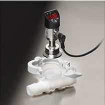
Our team at TBL is extremely proud to launch our aSURE™ instrument fitting, which was developed to provide a closed barrier between a fluid path and the external environment. This allows users to use gamma irradiation or other sterilization methods to sterilize an assembly, then install a pressure gauge at the point of use. The fitting is perfect for disposable manifolds and tubing assemblies used on hybrid single-use process skids and other equipment.

Fixed or tethered pressure-monitoring devices provide extremely high accuracy and are often hard-wired into a central control panel. The aSURE™ instrument fitting provides a practical means of providing a protective barrier on a complex manifold set without the need to have a gauge present during the sterilization process.

When comparing our aSURE™ fitting system to single-use pressure sensor technology, single-use sensors have many important drawbacks.

Drawbacks of Single-Use Pressure Sensors

  • Proprietary equipment required to relay the proper signal in to existing control systems
  • Generation of waste electrical and electronic equipment (WEEE)
  • Unable to use preferred pressure sensor in process

Benefits of the New aSURE™ Instrument Fitting

  • Use the pressure gauge of your choice on a single-use system
  • No need for gauge to be installed during sterilization process
  • No generation of waste electrical and electronic equipment (WEEE)
  • No proprietary monitor or transmitter/ line conditioning required
  • Integrate gauges from Anderson-Negele, WIKA, REOTEMP, Emerson Instruments, & Endress+Hauser

Designed for Pharmaceutical/ Bio-Pharmaceutical Manufacturing

Representative samples of each fluid contact material have been tested and have meet the following regulatory standards:

  • USP Class VI
  • Animal Derived Component Free (ADCF)
  • ISO 10993
  • REACH/ RoHS
  • California Proposition 65

Oina Peristalitc Pumps

TBL Plastics is proud to announce our partnership with Oina, an industry leading manufacturer and developer of peristaltic pumps. As the master distributor for our tubing products in Northern Europe, Oina has validated all of our pump-grade tubing in their pumps. With their technical knowledge and experience in the medical, diagnostic, industrial, and OEM markets. Oina is ideally suited to represent our products in these markets.

A Quote from Oina CEO, Anders Lovas:

“We have during the last year conducted TBL tube tests in multiple pump configurations and applications for several different tube dimensions with very satisfactory results. We have started selling and distributing TBL Pharm-A-Line tubes in analytical instruments, bio-reactors, process industries and pharmaceutical applications.”

Visit Oina.se or Contact Us for application assistance.


Oina Peristaltic Pumps